Kinematics is about computation of the tool-centre-point (TCP) out of joint angles and vice versa. First is simple, latter is more tricky, but lets see later on. But before starting any kinematics, it is necessary to define all coordinate systems.
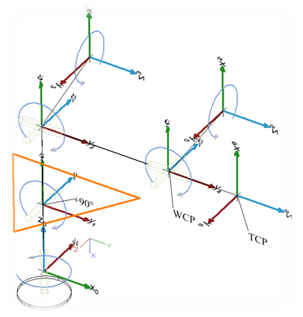
The most important design decision is to let the three upper axis’ intersect in one point, the so-call wrist-center-point (WCP). This decision makes the computation of the inverse kinematic solvable without numeric approaches.
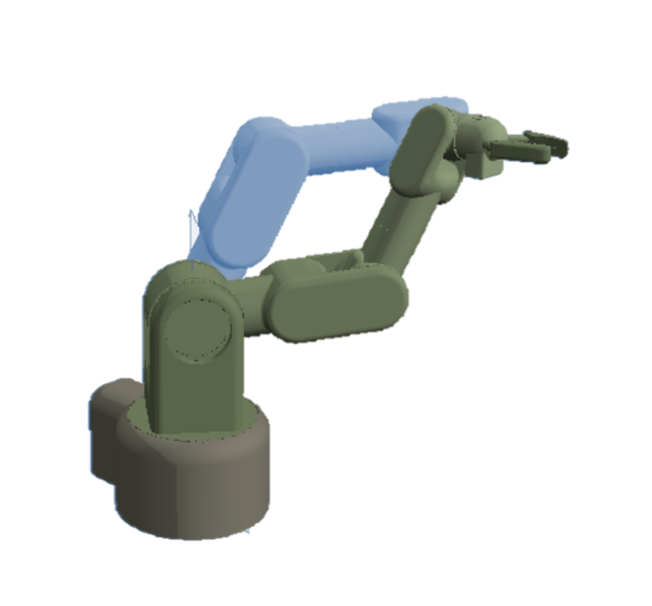
The picture shows the used coordinate systems in the default position of the bot, having all angles at 0°, starting from the base (angle0) and ending with the coordinate system of the hand (angle6). For convenience the forearm (angle1) adds +90° to the real angle in order to have the base position at 0° of the bot, although the illustrated actually is -90°. The coordinate systems have been are arranged according to the Denavit Hardenberg convention, which is:
The transformation from anglei to anglei+1 is given via
-
rotation around the x-axis by α
-
translation along the x-axis by α
-
translation along the z-axis by d, and
-
rotation around the z-axis by θ
So, the Denavit Hardenberg parameters are:
| Joint | a[°] | a[mm] | d[mm] |
|---|---|---|---|
| Hip | -90° | 0 | d0 |
| Upper arm | 0 | a1 | 0 |
| Forearm | -90° | 0 | 0 |
| Elbow | 90° | 0 | d3 |
| Wrist | -90° | 0 | 0 |
| Hand | 0 | 0 | d5 |
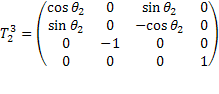
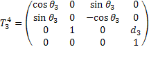
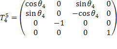
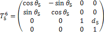
The general definition of a Denavit Hardenberg (DH) transformation is
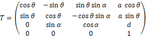
which is a homogeneous matrix with two rotations (x,z) and two translations (x,z).
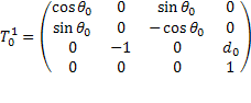
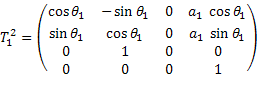
Combined with the DH parameters, the following DH matrixes define the transformation from one joint to its successor:
Forward Kinematics
With the DH transformation matrixes at hand, computation of the bot’s pose (i.e the position and orientation of the gripper) out of the joint angles is straight forward. The matrix representing the gripper’s pose  is
is
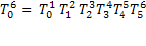
By multiplying the transformation matrix with the origin (as homogeneous vector), we get the absolute coordinates of the tool centre point in world coordinate system (i.e. relative to the bot’s base).

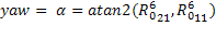
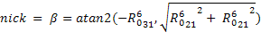
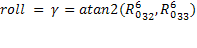
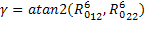
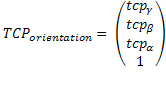
The orientation in terms of roll/nick/yaw of the tool centre point can be derived out of by taking the part representing the rotation matrix ( ). (Wikipedia Roll/Nick/Yaw )

For  we have a singularity (atan2 never becomes this), but wikipedia has a solution for that as well

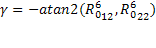
if  we get
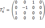
Note: Unfortunately, the gripper’s coordinate system is not appropriate for human interaction, since the default position as illustrated in the Coordinate Systems is not nick/roll/yaw=(0,0,0). So, in the Trajectory Visualizer it is handy to rotate the gripper matrix such that the default position becomes (0,0,0). The according rotation matrix represents a rotation of -90° along x,y, and z, done by the rotation matrix
In the following equations, this is not considered, since it is for convenience in the UI only, so you will find that additional rotation in the source code only.
Inverse Kinematics
Inverse kinematics denotes the computation of all joint angles out of the tool-centre-point’s position and orientation. In general this is hard, and giving a non iterative solution for a 6DOF robot is only feasable, when computation of the grippers position and the grippers orientation can be considered separately, i.e. the angles of the lower three actuators is not depending on the orientation of the gripper. Still, I do not like numerical solutions, even though with todays processors (or FPGAs) this is no more a question of computational power. I just think that a numerical solution is not a real solution but a surrender to complexity. That's why I let the upper three joint angles intersect in the WCP, which is a basic assumption of the following.
Input of inverse kinematics is the TCP’s position and orientation in terms of roll, nick, yaw, abbreviated by γ, β,and α.
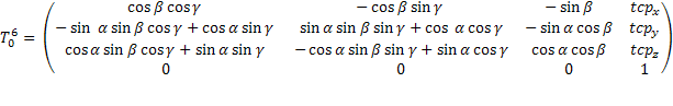
First, we need to compute the wrist-centre-point out the tool-centre-point. This is possible by taking the TCP and moving it back along the TCP’s orientation by the hand length. For doing so, we need the transformation matrix from the base to the last joint
which we can derive out of the TCP’s position and orientation.
To build the transformation matrix we need the rotation matrix defining the orientation of the TCP. This is given by multiplying the rotation matrixes for all axis (γ, β, α) which gives  (see also computation of rotation matrix out of Euler Angles).
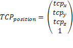
Now we can denote the transformation matrix of the TCP by building a homogenous matrix out of TCPorientation and TCPposition:
From the TCP’s perspective, WCP is just translated by d5:
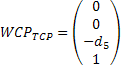
Furthermore, 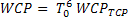 , so we get the WCP by
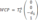
in world coordinates.
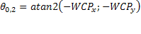
Having a top view on the robot shows how to compute the first angle θ0:
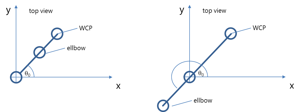
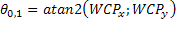
Actually, this angle exists in two variants: if the bot looks backwards, we get the formula above. But another valid solution is looking backward when we get
Thanks to the design having a wrist-centre-point where the axes of the three upper actuators intersect, the next two angles can be computed by the triangle denoted in orange:
Again, there are two solutions (aka configurations), one configuration corresponds with a natural pose of the elbow, solution II is a rather unhealthy position:
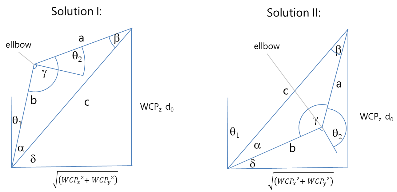
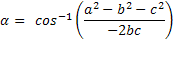
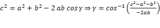
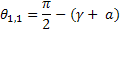
a and b is given by the length of the actuators a1 und d3. So, with cosine law we get the angles α and γ.
Finally, we get

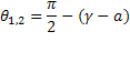
and the second solution

The upper angles θ4, θ5, θ5 can be obtained by considering the chain of transformation matrixes. With

we get
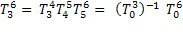
To ease the annoying multiplication  we only need to consider the rotation part of the homogenous matrixes, translation is no more relevant, since the orientation alone defines the three upper angles.
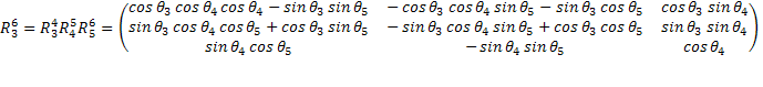
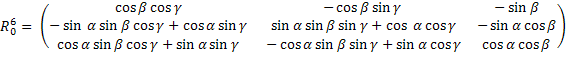
- and therefore the rotation part - is already known resp. can be obtained out of the given angles θ0, θ1, θ2 by
By equalizing the previous two equations we get a bunch of equations defining the upper angles, still these equations are hard to solve, due to the complex combination of trignometric functions. But, there are some equations which are simpler and can be solved for an angle. First angle that seems to be easily computable is θ4:
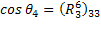
gives two solutions
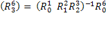
For θ3 there is no easy matrix element, but we can combine

to
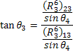
which ends up in
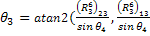
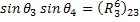
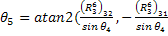
again having two solutions depending on θ4. Same is done on θ5:
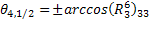
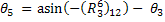
If θ4=0, we have an infinite number of solutions θ3 and θ5 (gimbal lock). In that case, we consider  :
:
 .
.
Since we know the trigonometric addition theorem from school

we get

We are free to choose θ3 and arbitrarily select the bot’s current angle θ3, such that this one will not move in that specific case.
In the end, we get eight solutions by combining the possible pose configurations of θ0(forward/backward), θ1 and θ2(triangle flip), and θ4(hand orientation turn).
The correct solution is chosen by taking the one that differs the least from the current bot’s joint angles.
What is with all the other equations from ? We could use them to invalidate some of the four solutions, but still there will remain a list of solutions we need to choose from. So, it does not really make sense to take this route.
The selection algorithm is quite simple:
-
consider only mechanically valid solutions, i.e. omit those that violate mechanical boundaries.
-
Compute an angle-wise "distance" to the current position and take the solution with the least distance, i.e. take the solution with the least movement.
The latter has the consequence that the pose will try to remain in a configuration and no sudden movements like a turn of 180° happens.
All this is implemented in Kinematics.cpp. But - as usual - trying out before implementing this is a good idea, so I did that in this spreadsheet.
Speaking of configurations: if you want to change the configuration of the bot, e.g. from elbow down to elbow up which includes turning the base by 180° the approach of having a linear movement from one pose to the other and interplating in between does not work anymore, since the start and end poses are identical, but with a different configuration.
First possibility to change configuration is to have a non-linear movement that interpolates angle-wise resulting in a weired movement that would be really dangerous in a real world:
So, you rather introduce an intermediate pose where you can safely turn the critical actuator (mostly the shoulder). This is not less expansing, but a more controlled way:
Thing is, that one has to go via a singularity (the upright position) which is normally avoided like hell. One reason is the way how we compute θ4=0, and a numerical reason that singularities are kind of a black hole, the closer you get, the more you are sucked into imprecisions of floating numbers since you approach poles of the underlying functions. So it is defininitely best to simply avoid changing configurations or getting too close to singularities.