Assuming that we have the trajectory defined in terms of a sequence of joint angles, we still need to translate that into movements of the motors. This translation should be done in a manner that no motors limits are violated, and with a speed profile that avoids vibrations by limiting the acceleration.
Additionally, we need a feedback loop to ensure that the to-be angle of the motor is actually reached.
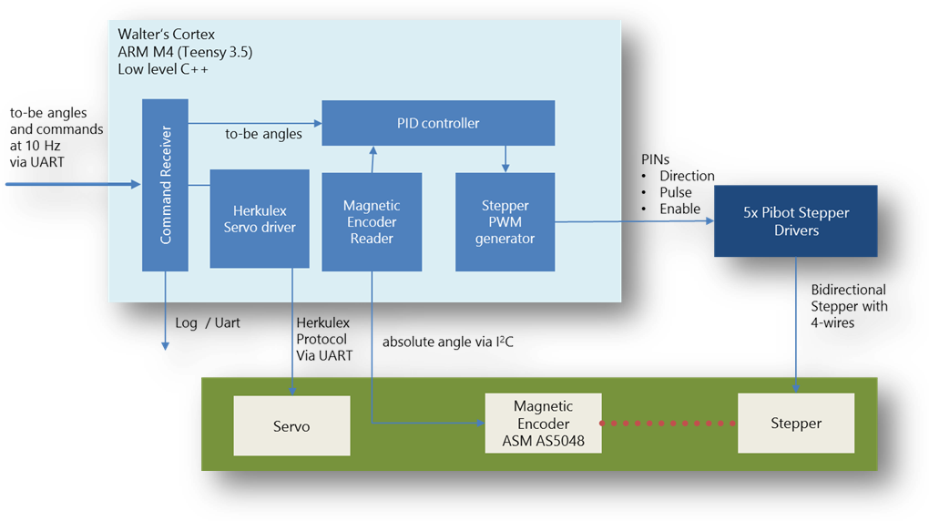
All this is done in Walters Cortex, a board based on an 32-bit ARM microcontroller (Teensy 3.5) that receives interpolated trajectory points at 10Hz, and runs a closed loop for the stepper motors at 100Hz. In that closed loop, the encoders are sampled reading the angle of each actuator with a precision of 14-bit = 0.02° generateing stepper impules that follow the trajectory. Furthermore, it takes care that no bumpy movements happen by limiting angle, speed, and acceleration. This should have happened during trajectory planning already, but you never know.
Schematics
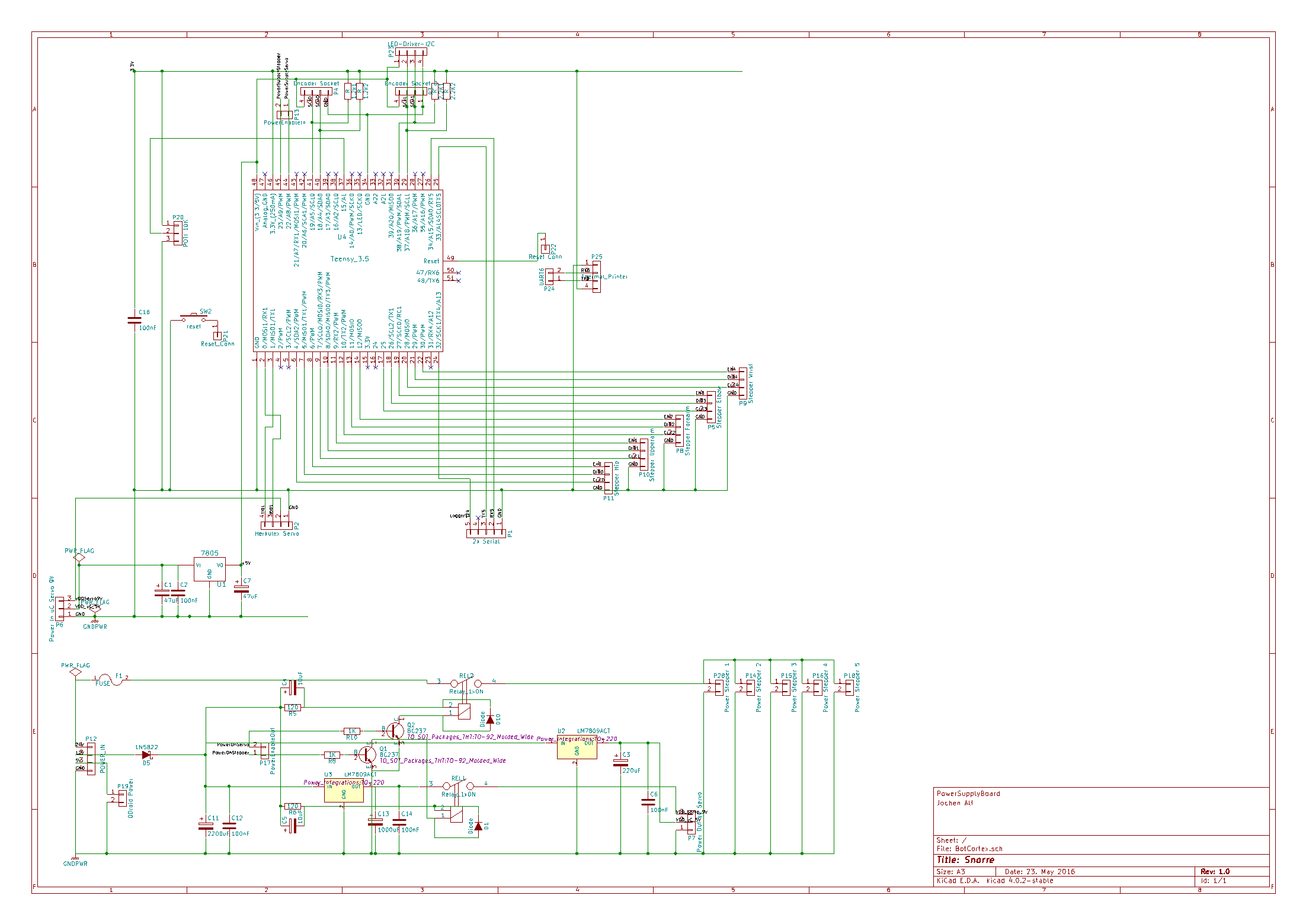
The lower part of the layout contains a separate power supply for the servos, the steppers and mC. The mC gets 5V by a standard integrated voltage regulator (7805), the two servos are driven by a 7809 voltage regulator providing 2A (two HerkuleX servos required 1A at most). Additionally, there are two relays for a proper start-up procedure switching the 240W power supply for the steppers and the power supply for the servos. This has been necessary to avoid impulses to the motors inducing annoying ticks when power is switched on. So, after booting the Trajectory Board and switching on the Cortex, all steppers are disabled, afterwards the steppers power supply is turned on, then the servos power supply is switched on. By that procedure, no ticks are happening during starting up.
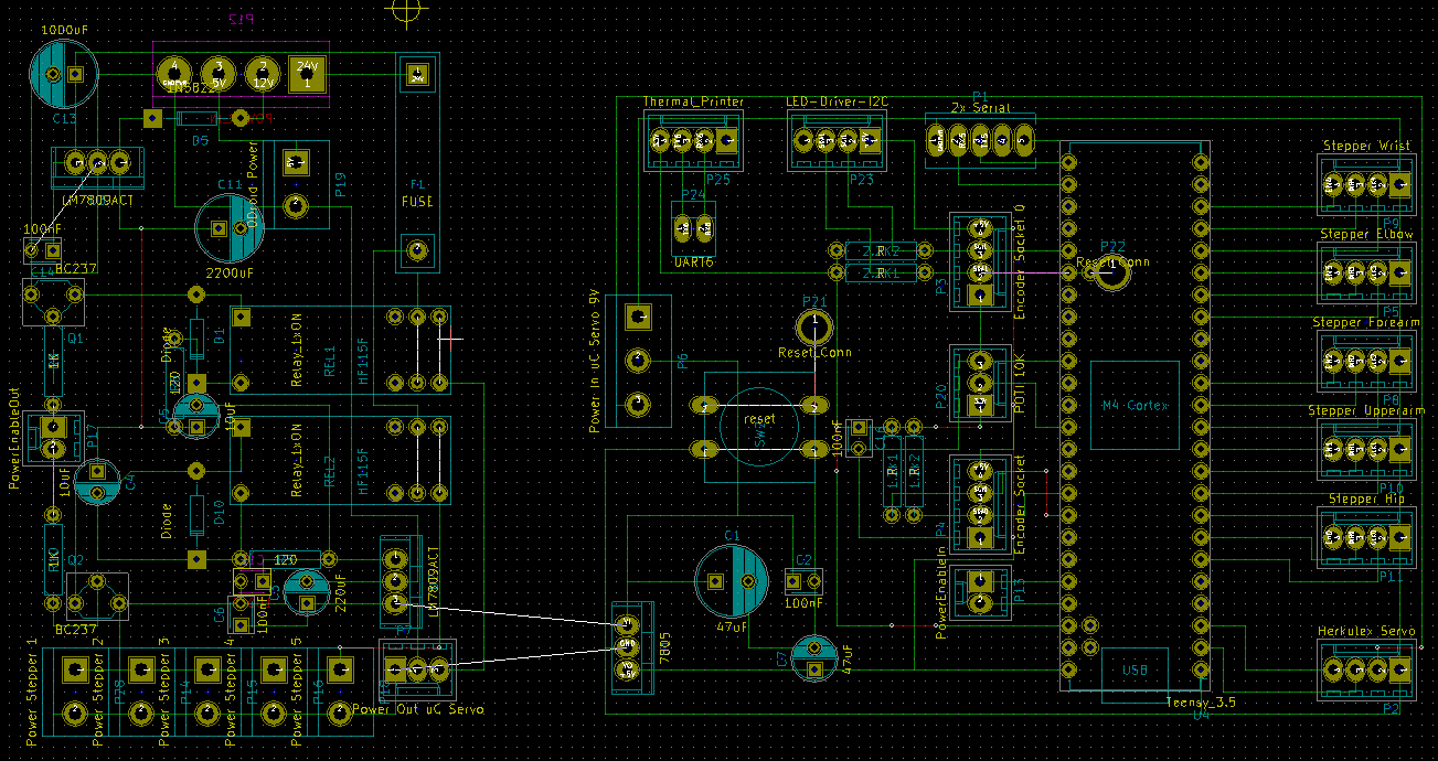
On top there is the Arm Cortex M4 controller. As usual, tricky part was to provide a stable power supply for all components. I struggled a lot with pikes induced by the strong steppers; particularily the magentic encoders respond very sensitive to voltage.
So, I made a separate board providing 24V/10A for the steppers (kind of overpowered, 6A would have been sufficient as well), 5V 4A for the Odroid XU4 and the Teensy 3.5, and 9V 2A for Herkulex servos. Servo’s and stepper’s power supply are turned on by a relay.
This is the PCB layout, which turned out to be rather simple. Especially the Teensy part consists more or less of sockets only:
Putting all together looks like this:
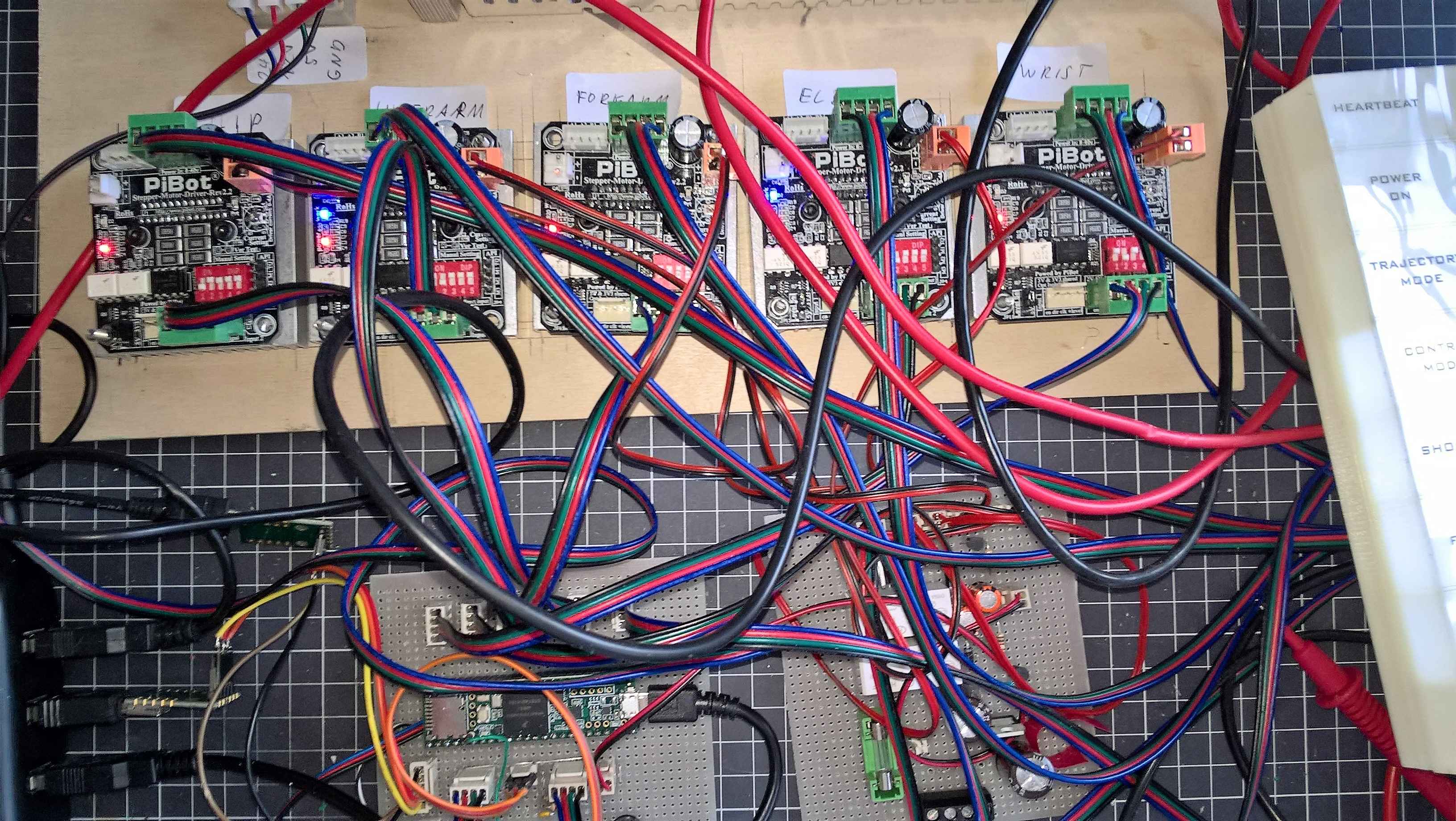
This is my desk with 5 Pibot drivers, a Teensy 3.5 (on the left bottom side) and the power supply PCB on the right. The wooden board is the backside of the control cabinet
Sensors
The used sensors are AMS' magnetic encoders 5048B with 14-bit resolution and an I2C interface. They are driven 3.3 V on two I2C buses. Walter has no electronics in its base, all is connected via a long cable of approx. 1.5m. In general, this is a bad idea, since the capacity of that cable alone is around 250pF. So, I had to use small pullup resistors of 1.1KΩ for both I2C lines (see also Computation of I2C pullup resistors to get sharp impulses on the I2C bus. Minimum is around 966Ω to not exceed 3mA in SDA/SCl lines.
Software
The software of the Cortex runs on the basis of the Arduino library. This is a legacy, since I started with an 8-bit ATmega controller before I upgraded to an Arm processor (This happened when I realized that controlling 5 steppers and encoders eats up much more computing power than I thought). The software is interfaced via UART and accepts these commands (most important selection):
SETUP [force]
Initializes steppers, drivers, encoders and servos. Does an initial calibration.
If not successful, power is switched off. If parameter force is used, this does
not happen, but everyhting initialized successfully is waiting for commands
POWER (on|off)
Turns on/off power of steppers and servos
ENABLE
Enables steppers, i.e. gives power to them assuming "power on" has been issued
already
MOVETO <angle1> <angle2> <angle3> <angle4> <angle5> <angle6> <angle7> <durationMS>
Moves the bot (assuming power is on and it has been enabled) to the given angles
within passed amount of time. This service is called at 10Hz by the trajectory
execution module (webserver).
GET all -> {<ActuatorNo> : n=<name> ang=<angle> min=<min> max=<max> null=<null>}
Returns the current state of the bot as a list return angle, min, max and null
value per actuator.
Steppers
While controlling robot servos is easy (everything is built in, even a PID controller, they only require a serial interface and a library), stepper motors are more difficult to control. While very tempting by providing high torque without a gearbox and a proper position even without encoders, they turned out to cost me many hours until they moved that smooth as expected.
First approach was the classical feed-back control system taking the encoder angle and the to-be angle of an actuator, giving that to PID controller, computing a correcting angle and giving that to the stepper motor. In the Arduino space, the standard library to control steppers is AccelStepper which can be used to implement that and leverage from the nice feature of smooth acceleration and deceleration.
This idea was bad. AccelStepper provides the method move(targetposition) that accelerates first and decelerates afterwards until the motor stops exactly at the targetposition. This works fine for larger moves of several seconds. But in a closed loop, this permanent acceleration and deceleration produced vibrations ending up in resonances. Speed was very limited not to mention a nasty sound.
The solution that finally worked was to compute the acceleration that is required in one sample of 10ms, and set this acceleration explicitly for the next sample:

vencoder is the speed that is necessary to compensate lost steps. It can be approximated by

Unfortunately, setting the acceleration requires a square root for computing the time until the next step (as done internally in AccelStepper)
This equation was the reason to decommission the previously used 8-bit Atmega and go to a 32-bit ARM processor with FPU which provides the square root computation in hardware.
The final closed-loop looks like this:
    void stepperLoop () {
        float dT = sampleTime();                         // [ms], approx. 10ms
        float currentAngle =        getEncoderAngle();   // encoder value in [°]

        // interpolate trajectory to get current and next angle
        float toBeAngle =           movement.getCurrentAngle(millis());
        float nextToBeAngle =       movement.getCurrentAngle(millis()+dT);

        // get speed of current sample, next sample and error compared to encoders angle
        float currStepsPerSample =  getMicroStepsByAngle(toBeAngle - lastToBeAngle);
        float nextStepsPerSample =  getMicroStepsByAngle(nextToBeAngle - toBeAngle);
        float stepErrorPerSample =  getMicroStepsByAngle(toBeAngle  - currentAngle);

        // implement PI controller. kP is 0.3-0.5, kI can be low (< 0.1) depending on mechanics
        float Pout = kP * stepErrorPerSample;
        integral += stepErrorPerSample * dT;
        float Iout = kI * integral;
        float PIDoutput = Pout + Iout;
        float accelerationPerSample = PIDoutput;
        float distanceToNextSample = accelerationPerSample + currStepsPerSample;

        // compute the acceleration for this sample
        float sampleAcc = ((currStepsPerSample-nextStepsPerSample+stepErrorPerSample) / dT;
        accel.setAcceleration(fabs(sampleAcc));      // do not accelerative faster than sampleAcc
        accel.move(distanceToNextSample);            // move n steps
    }
Source code is in WalterCortex, control loop above can be found in GearedStepperDriver.cpp.