Inverse kinematics, i.e. computation of joint angles out of the gripper’s position can be hard. If the design is too playful, nearly impossible complex. So, it is a good idea to ease the maths by having the upper three axes intersecting in one point. Later in the chapter on kinematics we will see that with that limitation kinematics becomes possible without having a mathematician at hand (still not easy, but feasible).
Dimensioning
Before starting the design it is necessary to calculate the torque in all actuators in order to select the steppers and gear ratios properly. In principle, this is simple: The gripper should be able to manipulate 500gr, the forarm has a length of 400mm and the upper arm a length of 350mm, assuming a certain weight per actuator the law of the lever allows to compute the torque of each motor. Tricky part is, that depending on the stepper you choose, the weight of an actuator changes. In the end I did that computation with excel, and came to these torques and gear ratios, which are used to select the stepper's dimensions.
| Actuator | Computed Torque | Gear | Min Stepper Torque | Selected Stepper Size | Act. Stepper Torque |
|---|---|---|---|---|---|
| Wrist | 0.6 Nm | 1:4 | 0.18 Nm | NEMA 17 42x42x39 | 0.4 Nm |
| Elbow | 0.6 Nm | 1:7 | 0.11 Nm | NEMA 17 42x42x25 | 0.17 Nm |
| Forearm | 11 Nm | 1:14 | 0.8 Nm | NEMA 24 60x60x57 | 1.9 Nm |
| Upper arm | 34 Nm | 1:18 | 1.8 Nm | NEMA 24 60x60x87 | 3 Nm |
| Hip | 8 Nm | 1:9 | 0.9 Nm | NEMA 23 57x57x56 | 1.2 Nm |
The steppers are always placed in the previous joint of an actuator in order to move the centre of gravity away from the biggest lever. So, the three heavy steppers actually do not move but turn only when the arm goes up or down.
Design Patterns
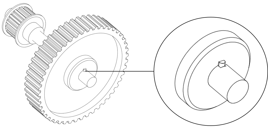
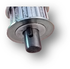
With that amount of torque, shaft-hub joints need to be really stable. While the small steppers have the pulley connected with grub screws, the big ones need something different. Although a lot of filing was involved, I went with feather keys for the middle shaft of gearboxes and the connection between stepper motor and timing pulley.
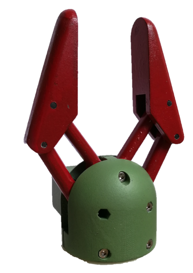
Gripper
Due to space limitations, it seems to be appropriate to use a servo for the gripper. I used a standard design principle where one lever is driven, and the other lever mirrors the movement by a gear wheel. The servo is hidden in a small box, it is a HerkuleX Robot Servo with 0.12 Nm (today I would take the stronger version of the same servo, 0.12Nm is just enough to lift a beer).
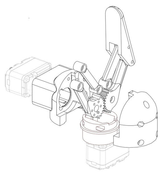
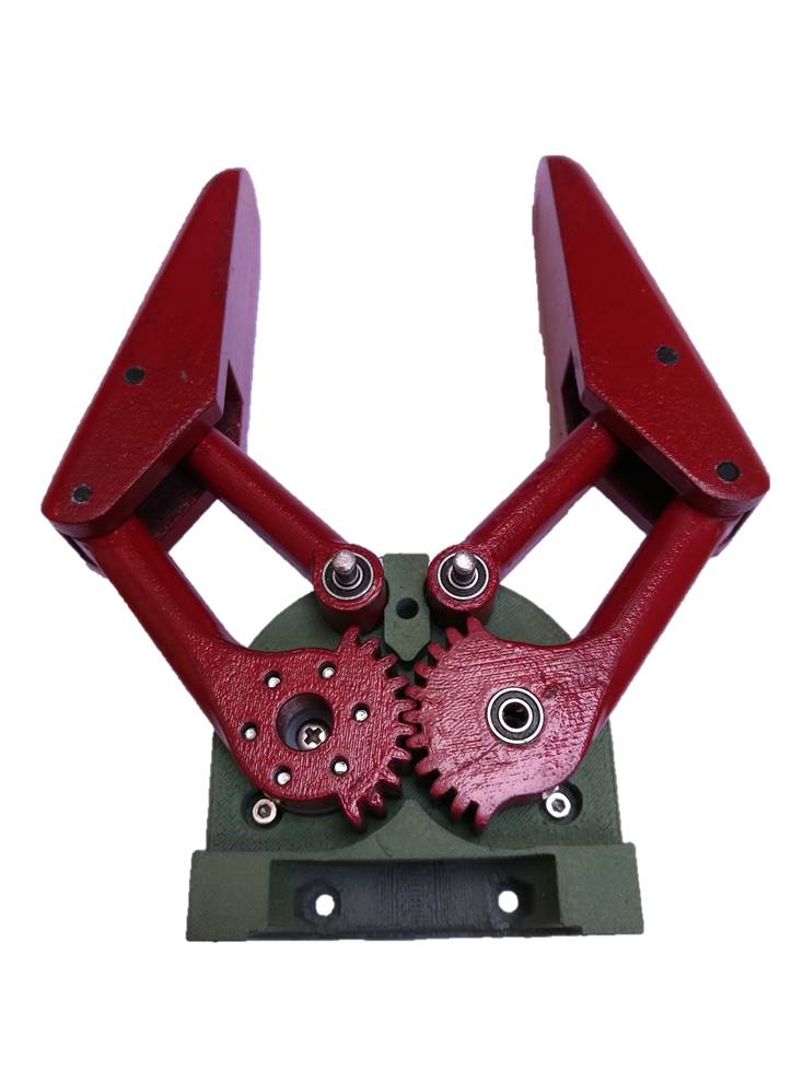
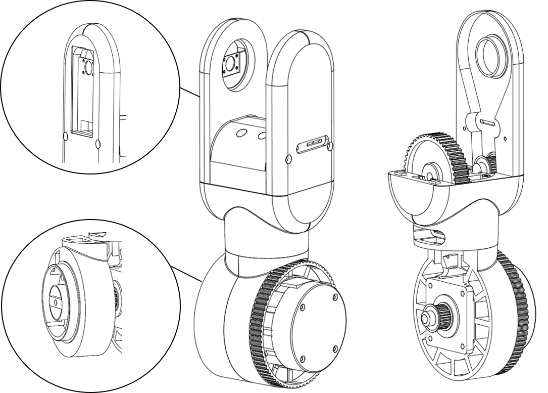
Assembly has to start from the top, not for mechanical reasons, but due to the cables that are all placed inside the robot going down from the gripper to the base. The gripper has bearings in all moving parts. The left gearwheel has the servo behind, mounted on the enclosed servo disk. To increase stability, the hole over the servo screw is used for another bearing to lock this lever from both sides in its position.
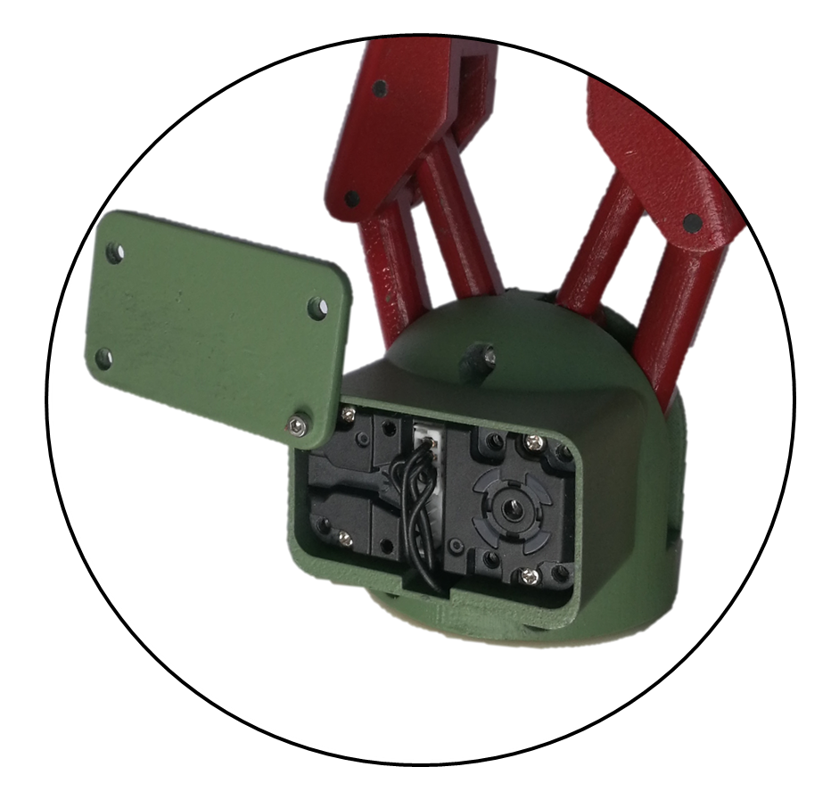 The servo's cable is going through the servo housing into the flange where the wrist will be placed.
I'm still not really happy with the gripper. Although it works fine, the bulge containing the servo is really ugly. But, the space below the gripper is already occupied by the servo turning the wrist, unfortunately. I played with other design types, but always came back to this one due to its simplicity.
Wrist
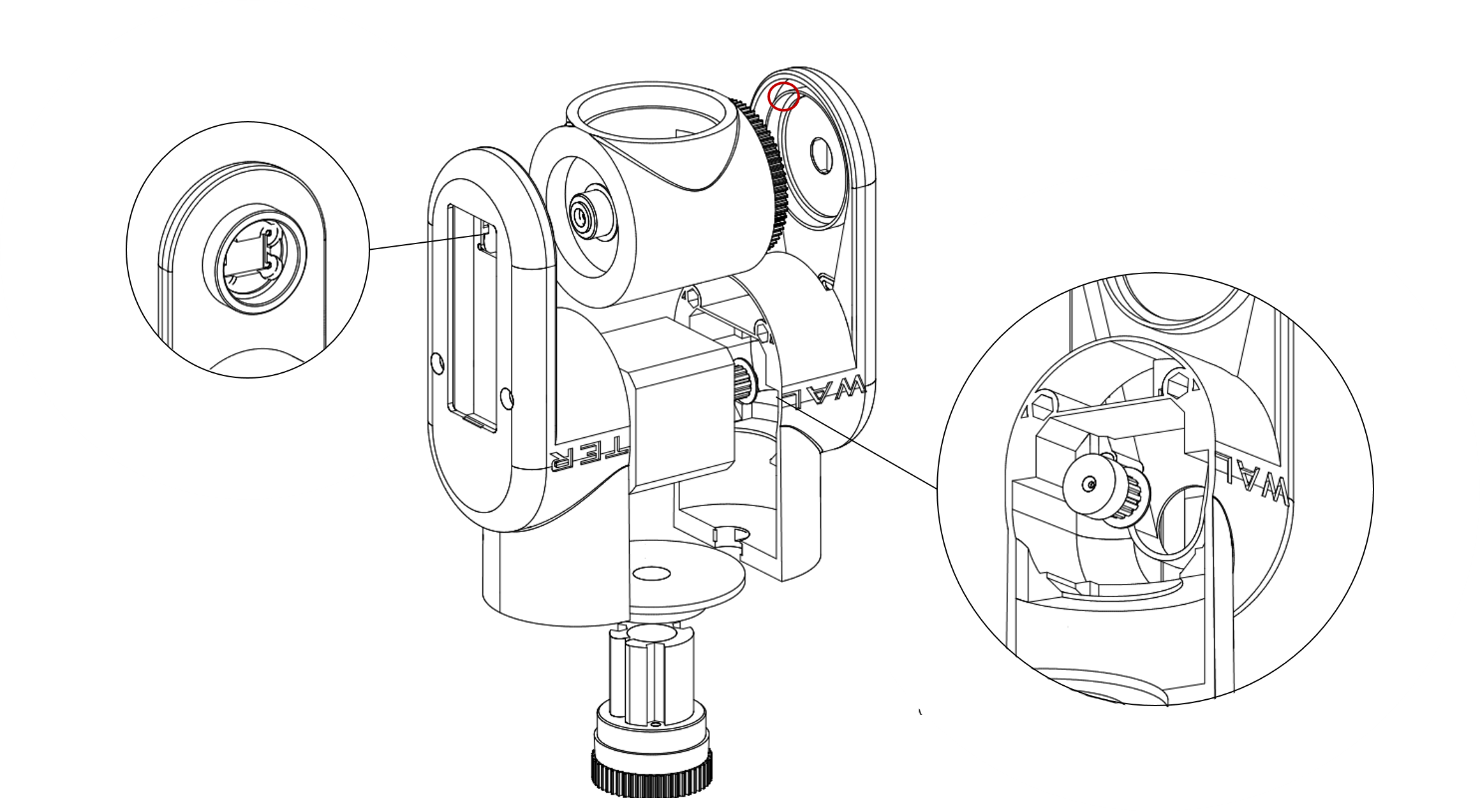
The wrist is also designed with the same servo. A small flange connects the wrist with the two halves of the gripper housing, the hole hides the cable of the gripper servo. Worth to mention is that bearings at both sides of the wrist have a different size, since the servo looks through the inner hole of the bigger bearing. On the other side, in the middle of the smaller bearing there is the hole for the magnet used by the magnetic encoder of the forearm. The cable of both servos (gripper and wrist) is going through the wrist underneath the servo.
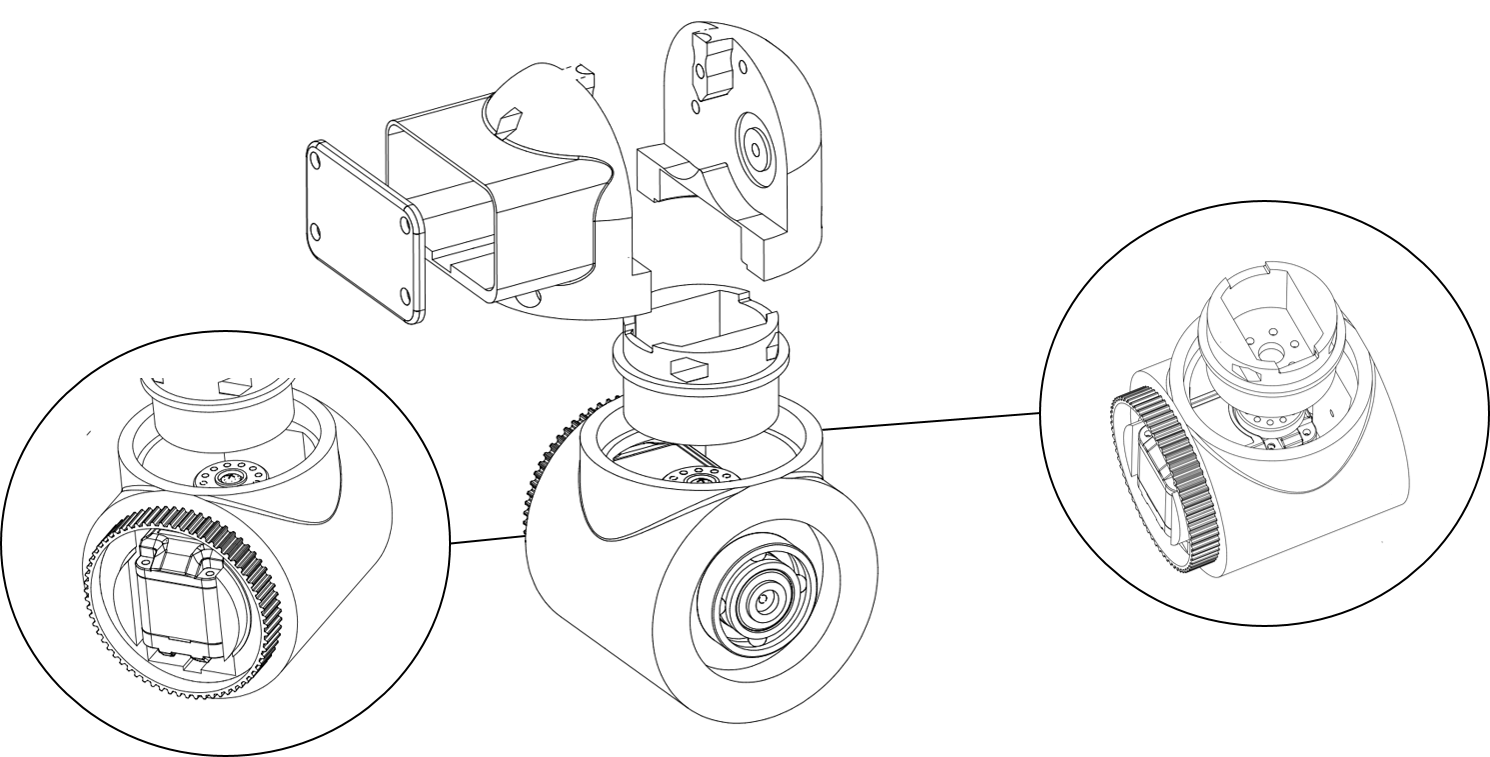

 The gripper is held with only one extra loose bearing, since the servo provides the fixed bearing already. The servo is mounted on the back of the wrist with screws. The servohorn is mounted to the flange that links the wrist to the gripper.
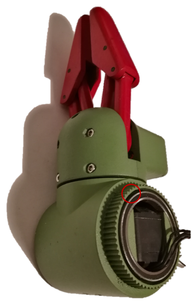
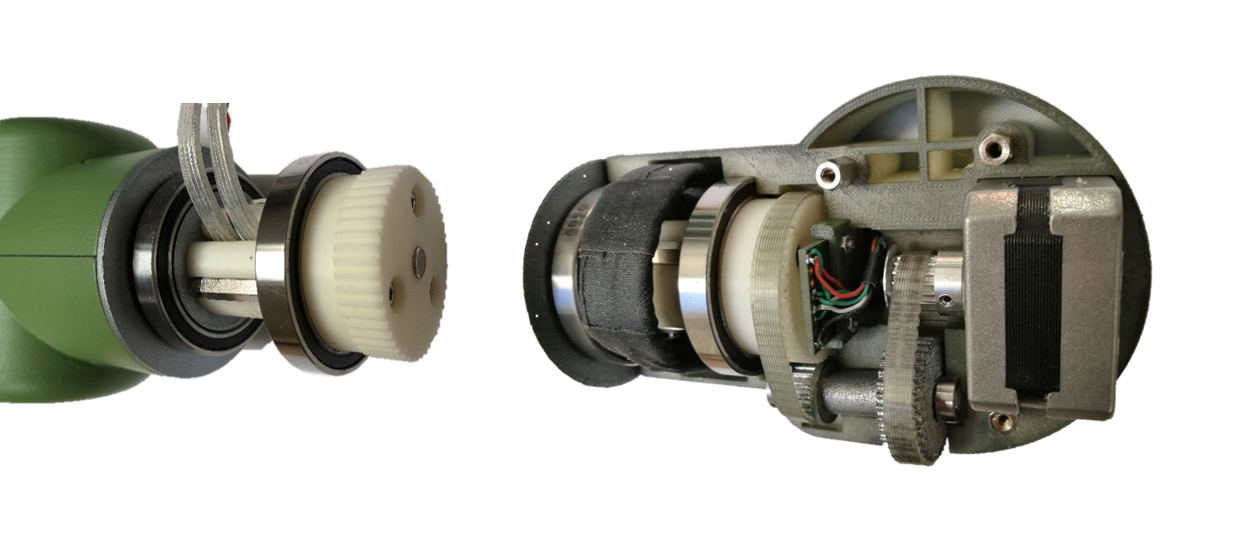
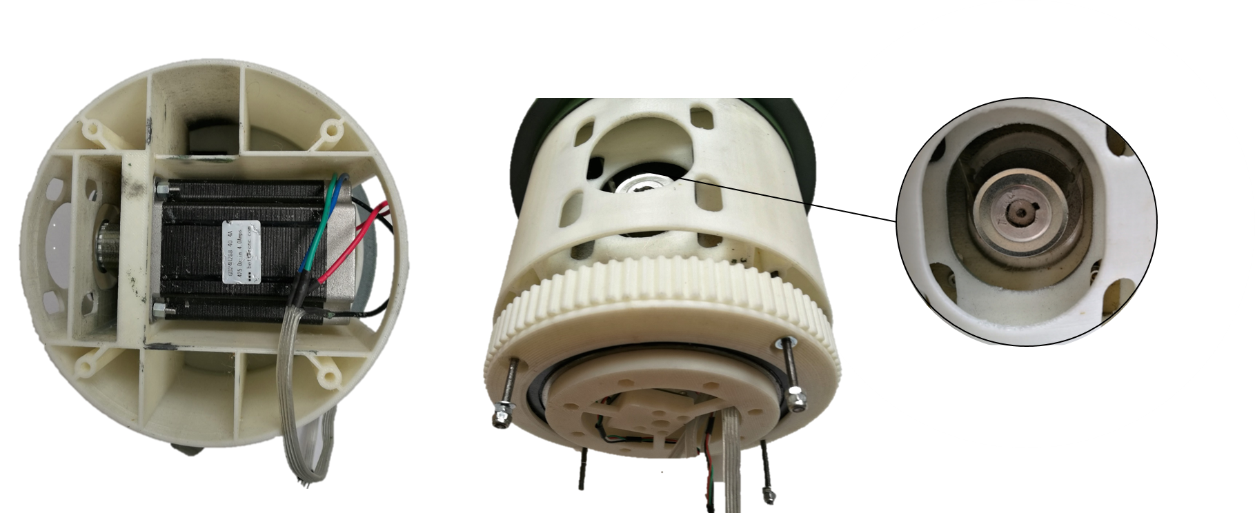
The bearing at the right side, that is marked with a red circle is very close to the inner diameter of the belt pulley. This space is occupied by the forearm to fix the bearing with a thin ring. The ring can be seen on the following CAD drawing, also marked with a red circle.
Forearm
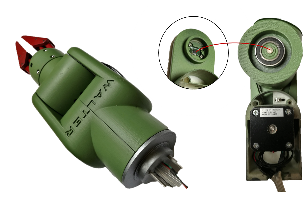
The forearm is more complex, since it drives the wrist with a belt drive and a stepper motor. The belt drive has a gear ratio of 1:4. It is held tight with a spanner. At the other side of the wrist, the magnetic encoder is located. All cables are meeting in the room below the stepper at the bottom, and going down through the hole of the disk.
Below, the magnet in the middle of the wrist's bearing can be seen, which has a distance of 1mm to the magnetic encoder of the other half of the forearm.
Elbow
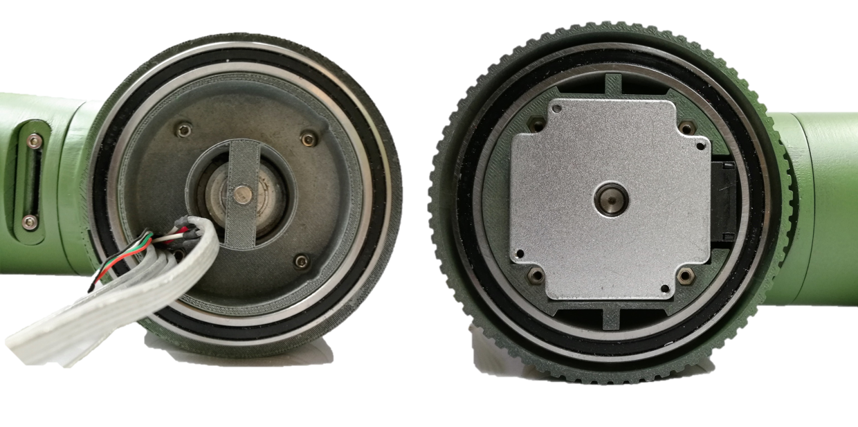
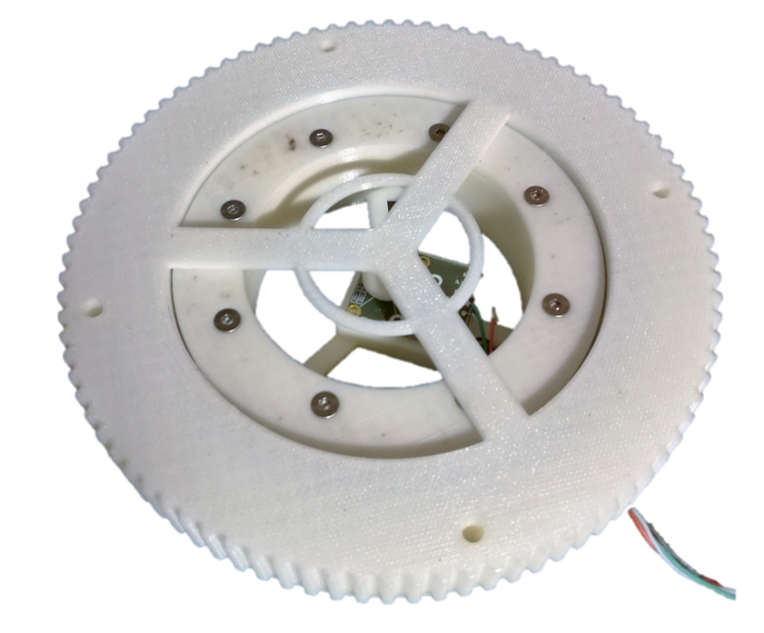
The elbow consumed most design-time, it is a two stage belt-drive with a ratio of 1:7 and a stepper with 17Ncm. The flange in the middle is the connection to the forearm. It is mounted with two bigger bearings and has a cable channel that gives space to a self made cable drag chain that allows to have the cables inside, since the centre of the axis is occupied by the encoder already.
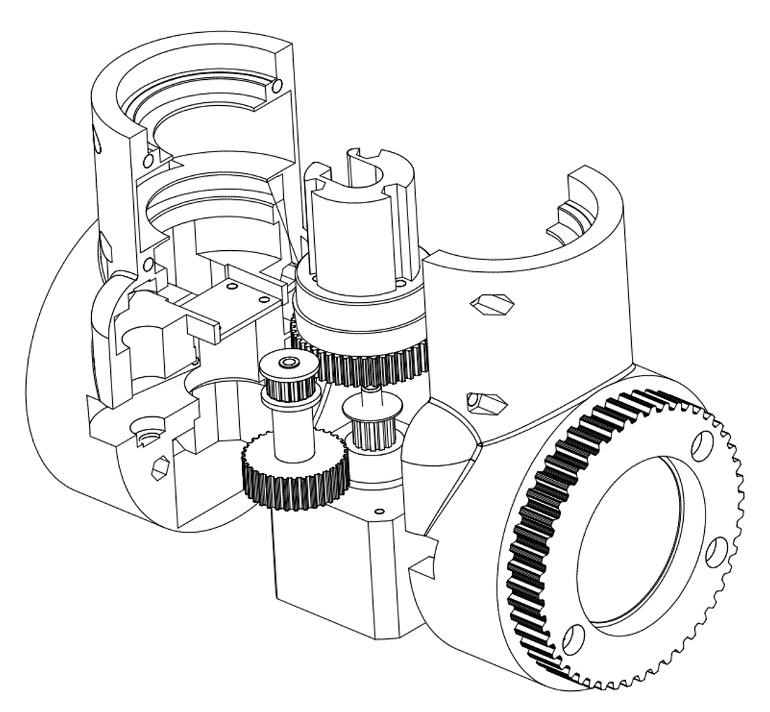
This picture shows the inner construction and the cable drag chain. The magnet in the centre of the flange is right opposite to the encoder, the small PCB in the middle of the ellbow.
At first, I tried to hide the belt pulley within the enclosure, but later on I got the impression that a peep hole exposing a pulley moving faster than the elbow could be a nice technical touch.
Upper Arm
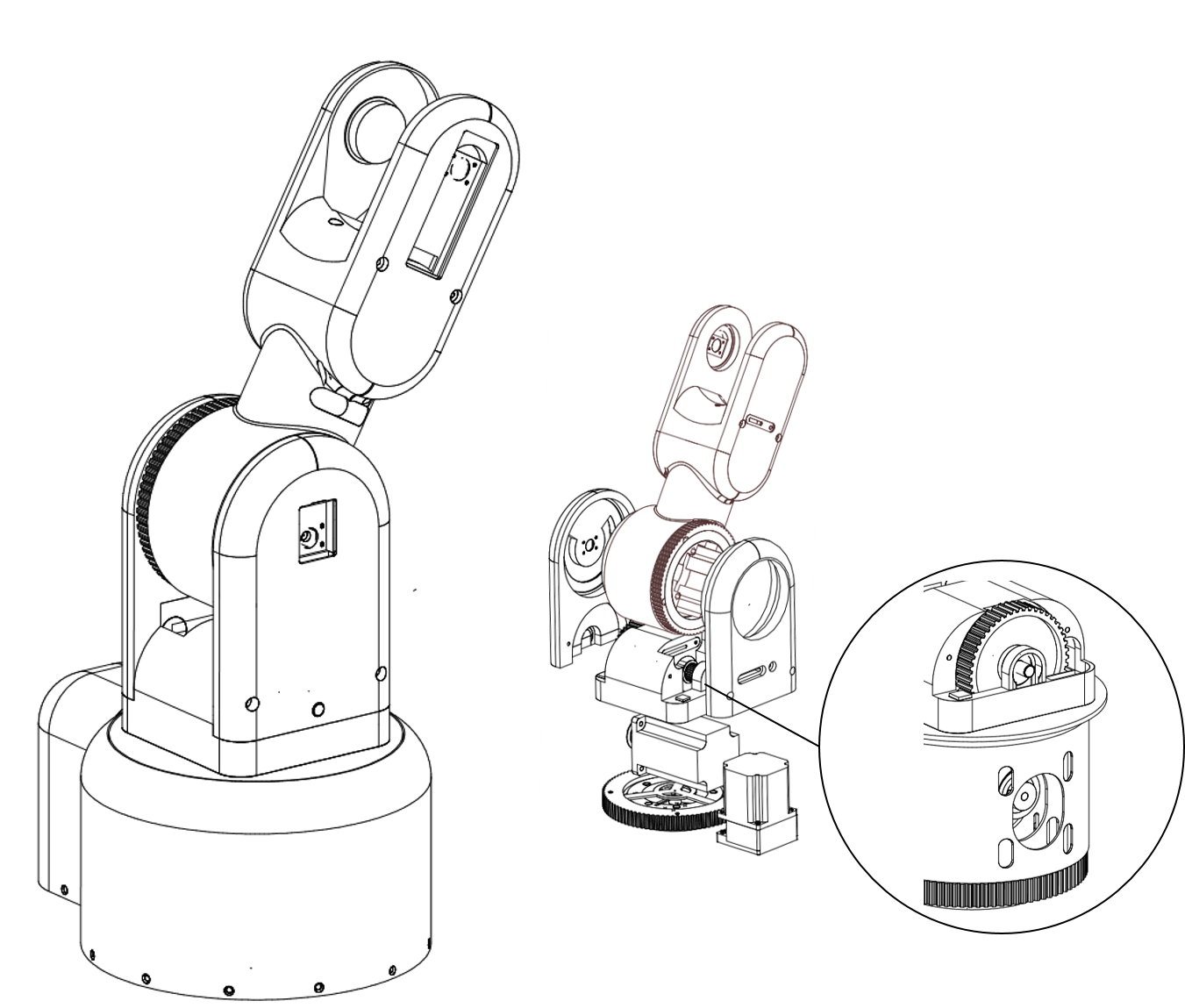
The upper arm contains a strong stepper with 1.9Nm and a two-staged gear with a ratio of 1:14. On the left side a magnetic encoder samples the angle of the ellbow, above the encoder and the cable channel is located. The cables are going down through a hole in the middle block down to the left side of the bttom part. The ride side contains the belt to the elbow. All belts are tighened with a clamp that can be adjusted from outside.
The cable is going through the centre of the axis. Below the fork of the upper arm, the gearbox is placed.
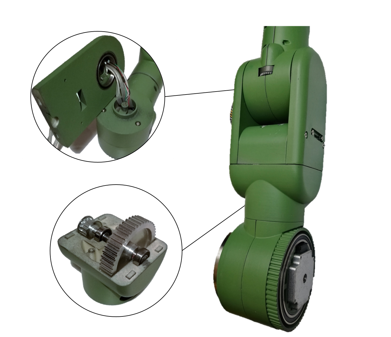
Right above the belt pinion of the stepper, the magnet for the encoder is placed, in the middle of the space intended for the cables. The thin space between the bearing and the housing will be required by the shoulder actuator to hold the upper arm.
Shoulder
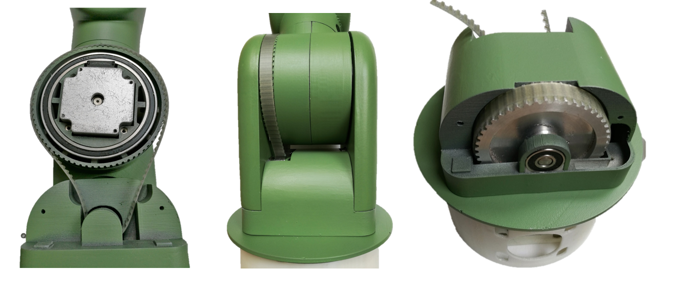
The shoulder contains the strongest stepper moving the upper arm with approx. 3 Nm. A gear ratio of 1:18 could deliver 50Nm, but this number is rather theoretical, since 3D-printed parts would not survive this. But, this allows to reduce the current and use micro-stepping improving the movement.
On the left flange, there is a segment-shaped cable channel below the location of the magnetic encoder. The right flange has a big hole to make room for the stepper's backside. This is hidden by a lid that rotates with the upper arm, which gives a nice technical touch. Inside the middle block between the flanges, there is a shaft with two drive pulleys for the two-staged gearbox, same construction as in the upper arm.
Hip
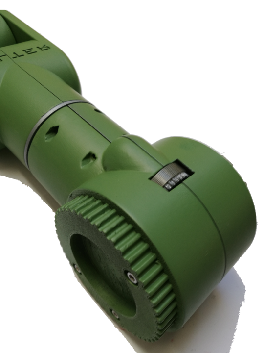
Finally, the hip stepper is what makes the housing of the shoulder look like an iglu. It is a simple belt drive to the shoulder. The shoulder is residing on a drive pulley disk that is mounted on a big bearing.
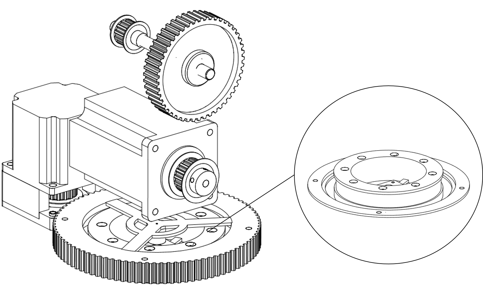
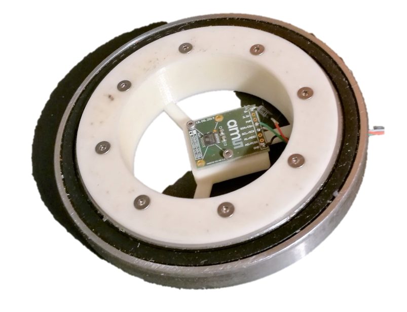
The encoder is mounted within the inner base, the magnet is mounted at the outer belt wheel, in between is a big bearing.
Housing
The housing of the shoulder is not only to hide the hip stepper, but also to stabilize the shoulder by having lots of small bearings on the top edge supporting the shoulder. The inner compartments of the flower pot is filled with iron grain, which has a mass of approx 5kg
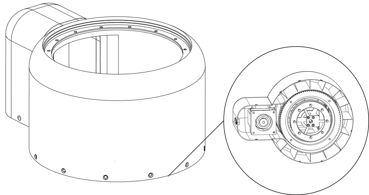
The middle layer of the pot is not printed but made of wood for stability reasons. Besides that, I like the look of birch plywood:

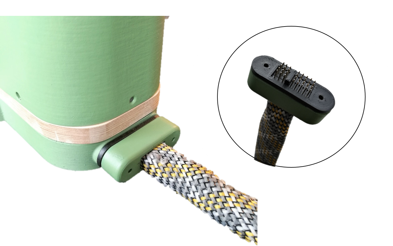
Cable
Last but not least, a beautiful cable sleeve accompagnies Walter's color. Since all electronics is in the control cabinet, the cable has 5x4 pins for the steppers, 4 pins for the servo's serial connection and 2x 4 pins for the two I2C busses.